| |
|
Description
The HPC Explorer is a small low-cost demo board from Microchip for the High
Pin Count general purporse PIC18FXXX family of microcontrollers.
The board includes a 80-pin PIC18F8722, a potentiometer, RS232 serial interface,
one user pushbutton, some LEDs and a header connector for PICtail add-on boards.
The HPC Explorer can also be used to evaluate the PIC18 J-series 3V devices
available in a Plug-In Module that fits in the header connectors around the
existing MCU.
Microchip offers an Ethernet PICtail board that can be connected directly
into the PICtail interface available in the HPC Explorer. Be aware that there
are two different models of the Ethernet PICtail, the regular one and the
"Plus" which is smaller, only 3.3V and intended for boards such as the
Explorer 16 with a complete different PICtail interface.
This project will show you how to configure the HPC Explorer board to be able to
run a modified version of the latest Microchip TCP/IP stack.
Design considerations
I don't have an Ethernet PICtail and unfortunately the HPC Explorer does not
provide any area on the PCB for prototyping, I decided then to put together
a small adapter board to use the PICtail interface to interconnect the HPC
Explorer with the nic28 ENC28J60 board
from LJCV Electronics and add an 8-pin socket for a serial SPI EEPROM such
as the 25LC1024 or the lower capacity 25LC256.
Initially I used the +5V supply available on the PICtail interface to power
the ENC28J60 on the nic28 and the serial EEPROM, but while the voltage
regulator on the HPC Explorer can handle the load its package is SOT-223
with almost no copper on the board to permit a reliable thermal dissipation,
then I added an external 5V regulator on the adapter board and modified
the HPC Explorer cutting the +5V line going to pin 26 of the J3 connector and
added a wire from that pin directly to the output of the CR1 bridge rectifier.
|
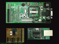 Figure 1
[Click Image to Enlarge]
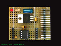 Figure 2
[Click Image to Enlarge]
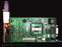 Figure 3
[Click Image to Enlarge]
|
Figure 1 shows all the different pieces, the HPC Explorer, the adapter board
and the nic28, Figure 2 a close up of the adapter board and Figure 3 the
nic28 mounted on the adapter board and the whole thing mounted on the PICtail
interface connector J3.
Figure 4 below shows a detailed schematic of the PICtail adapter board.
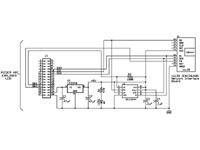
Figure 4
[Click on the image for a larger view]
|
Getting the board up and running
Compiling the firmware is not a huge or complicated task, it requires few
software tools available for download from Microchip's
website at no cost, and obviously the TCP/IP stack source code distribution and a
PIC programmer. For this project I used Microchip's
MPLAB ICD2 as a programmer.
With the latest modified version of the
Microchip TCP/IP Stack v3.75, the process is quite simple.
This new version adds the HPC_EXPLORER macro definition that
combined with the device selection for the Microcontroller generates the appropriate
code for this particular project.
The software distribution includes the MPLAB IDE project file
HPC_EXPLORER.mcp, load this project into MPLAB IDE,
select the correct processor (by default the project has selected the PIC18F8722)
and verify that the settings on the config.h and
hpc_explorer.h files apply to your project or modify them
accordingly (both files are located in the include
subdirectory of the main src directory).
For additional details check the README.TXT file
included in the software distribution.
For a detailed explanation about how to build Microchip's TCP/IP stack
for this or similar projects
Click Here.
|
Datasheets for relevant parts used in this project
 |
| |
|
©2006-2009, Jorge Amodio, All rights reserved
|
Last Update: Jan 28, 2008
|
|
|
|