| |
|
Description
Adding a character LCD module to any embedded design is not a daunting task. Today
there are many LCD manufacturers such as Optrex, Hantronix, Microtips, etc, that
offer a variety of character LCD modules with a parallel interface based on the
old Hitachi HD44780 or its Samsung cousin KS0066 controllers.
The HD44780 parallel interface became sort of a de facto standard for
communicating a microprocessor or microcontroller to a dot matrix character display,
this interface is also being used today for some vacuum fluorescent displays (VFD).
The interface consists on a 4 or 8 bit bidirectional data and address bus, and three
control signals, Enable (E), Register Select (RS to gain access to the controller
registers or via DMA to the character RAM buffer) and Read/Write (RW to select the
direction of the operation and bidirectional bus).
|
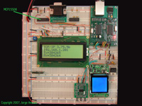
eIP-10 + 4x20 LCD via SPI
[Click Image to Enlarge]
|
But what do you do if you are short on I/O pins but have a SPI interface that can be
shared ?
This project shows an example about how to add a character LCD module to the LJCV
Electronics eIP-10 Board running the Microchip TCP/IP Stack using a Microchip
MCP23S08 port extender to connect the LCD module via the SPI interface.
Design considerations
The Microchip MCP23S08 8-bit port extender chip costs less than a buck and
can help you to extend the I/O capabilities of your design using the SPI
interface to communicate with it (Microchip has a similar device with an I2C
interface and both are also available in a 16-bit version).
Obviously this require some additional lines of code and a few more cpu
cycles and sharing the SPI interface, but the performance on the main
application is minimal and for a low pin count device presents a very
viable alternative to add more I/O ports.
Then for this project we will drive the 4-bit data bus and control signals
for the LCD module from the MCP23S08 requiring only one I/O pin for the
Chip Select (CS) of the port extender.
There is no need to read back any data from the LCD since we will be
using delays instead of checking for a BUSY state (the LCD driver routines
for the TCP/IP Stack must be non blocking to permit cooperative multitasking)
then we can tie R/W to gnd and we will be using the MCP23S08 only to write
to the LCD, but MCP23S08 implements a full bidirectional I/O port with some
extra features like generating interrupt signals on port status change, etc.
For this project I used a Hantronix HDM40216 4x20 display module. The
picture above shows the eIP-10 board on the top right and the LCD on the
left mounted in a prototype breadboard and a DIP version of the MCP23S08 on
the top left. Ignore the extra LCD on the bottom right, it's part of future
project showing how to drive a color graphics LCD.
Then we will use only the RB0 I/O pin to drive
CS of the MCP23S08.
A detailed schematic showing the connections from the MCP23S08 to the LCD
is available in the links section below.
|
Getting the board up and running
The latest modified version of the
Microchip TCP/IP Stack v3.75 includes a different set of LCD drivers than
the original version. The new driver is more versatile and easy to configure
and includes the option to write to a local character memory buffer (as used in the
TCP/IP Stack code) or directly to the LCD memory buffer.
The software also includes the driver for the MCP23S08 port extender and
the option for the character LCD driver to use it as the interface to the
display.
The hardware configuration is defined in the eip10_spilcd.h
include file which for the LCD configuration using the SPI interface includes
the following macros:
//***************************************************************
// LCD Module features and configuration
//
#define USE_LCD
#define USE_CM_LCD // Include Character Mode LCD Driver
#define LCD_USE_BUFFER // Enable local RAM LCD Buffer
//#define LCD_USE_CGCHARS // Enable Custom Characters support
#define LCD_USE_SPI
#define LCD_4BIT_IFACE
#define LCD_ROWS 4
#define LCD_COLS 20
#define USE_MCP23S08
#define PORTX_CS_IO (LATBbits.LATB0)
#define PORTX_SPI_IF (PIR1bits.SSPIF)
#define PORTX_SSPBUF (SSPBUF)
#define PORTX_SPISTAT (SSPSTAT)
#define PORTX_SPICON1 (SSPCON1)
#define PORTX_ADDRESS (0x00)
#define PORTX_SPICON1_CFG (0x20)
#define PORTX_SPISTAT_CFG (0x40)
Make sure that this configuration reflects your circuit and LCD geometry
(rows & columns), and remember to properly set the initial values for
the direction and initial state for the I/O port in the GPIO Ports assignment
section.
This new version adds the EIP10 macro definition that
combined with the device selection for the Microcontroller generates the appropriate
code for this particular project.
The software distribution includes the MPLAB IDE project file
EIP10.mcp, load this project into MPLAB IDE,
select the correct processor (by default the project has selected the PIC18F2620)
and verify that the settings on the config.h are
consistent with your project and that for the EIP10 you are including the
eip10_spilcd.h header file.
For additional details check the README.TXT file
included in the software distribution.
For a detailed explanation about how to build Microchip's TCP/IP stack
for this or similar projects Click Here.
|
Datasheets for relevant parts used in this project
Useful Links
TCP/IP Stack Source code and useful software tools
Additional Resources
|
|
|